Motivation and context
Motivation for this post aroused by the necessity of automating the time consuming task of defining constrains for riveted structures in Ansys Mechanical for an example case study.
Challenges I faced
So, to put things clear, I’ve got a 3D model with a few dozen sheet metal parts with corresponding holes for the rivets that should keep everything together and I need to individually define a constrain in Ansys Mechanical for each rivet to prepare the model for the structural analysis. I spent an afternoon manually performing the task and studying the command palette in desperate hope to find some useful automation after which I decided the problem was worthy of being dealt with seriously.
Brainstorming
I knew this task could be automated. I spent a lot of time at University working with APDL and I knew enough of Ansys for being sure about that. The first idea which came up to my mind was to try reproduce the same constrain by command line in APDL and then use an APDL command snippet in Mechanical. A little bit of research showed me that this was not possible since APDL command snippets in Mechanical can be executed only to operate on the solution information, not on the model preparation (even if the solution itself is obtained leveraging APDL under the Mechanical interface).
So the operation had to be automated inside Mechanical, there was no easy way out. Mechanical has got an Automation palette whose purpose is exactly that of let the user automate tedious tasks and there’s even a python command line interface to be used with the provided API, but my attention was caught by the Object Generator palette. That was the easy solution I was looking for.
Research
A little bit of investigation taught me that Object Generator works by applying user-defined structures to whatever element is indicated by appropriate named selections, so my attention switched to that subject: if I could find a way of grouping the holes edges of each sheet metal part into a named selection I would have my problem solved!
Even in this case I was sure that the named selection definition could be automated and I also found that when saving Mechanical outputs to be read by APDL the defined named selections are actually read by APDL as CM COMPONENTS. But in this case I found an easier solution directly inside Mechanical: named selections Worksheet definition. By setting some filters and operations, it’s actually possible to quickly define named selections for the interested items. At this point using Object Generator makes it easy to define whatever contact type needed.
Useful lessons I learned
In the above paragraphs I explained my motivation and the path which led me to the solution of my problem, here I’ll quickly provide useful hints by mean of an example study (the kind of thing I was desperately looking for when I started this little journey).
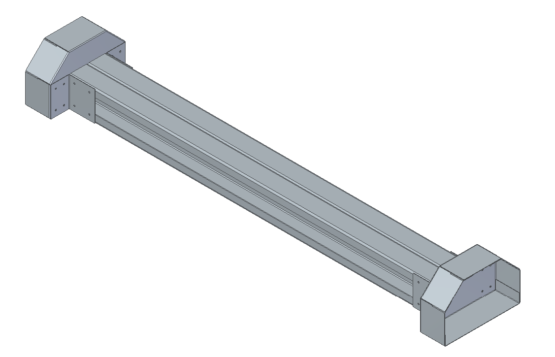
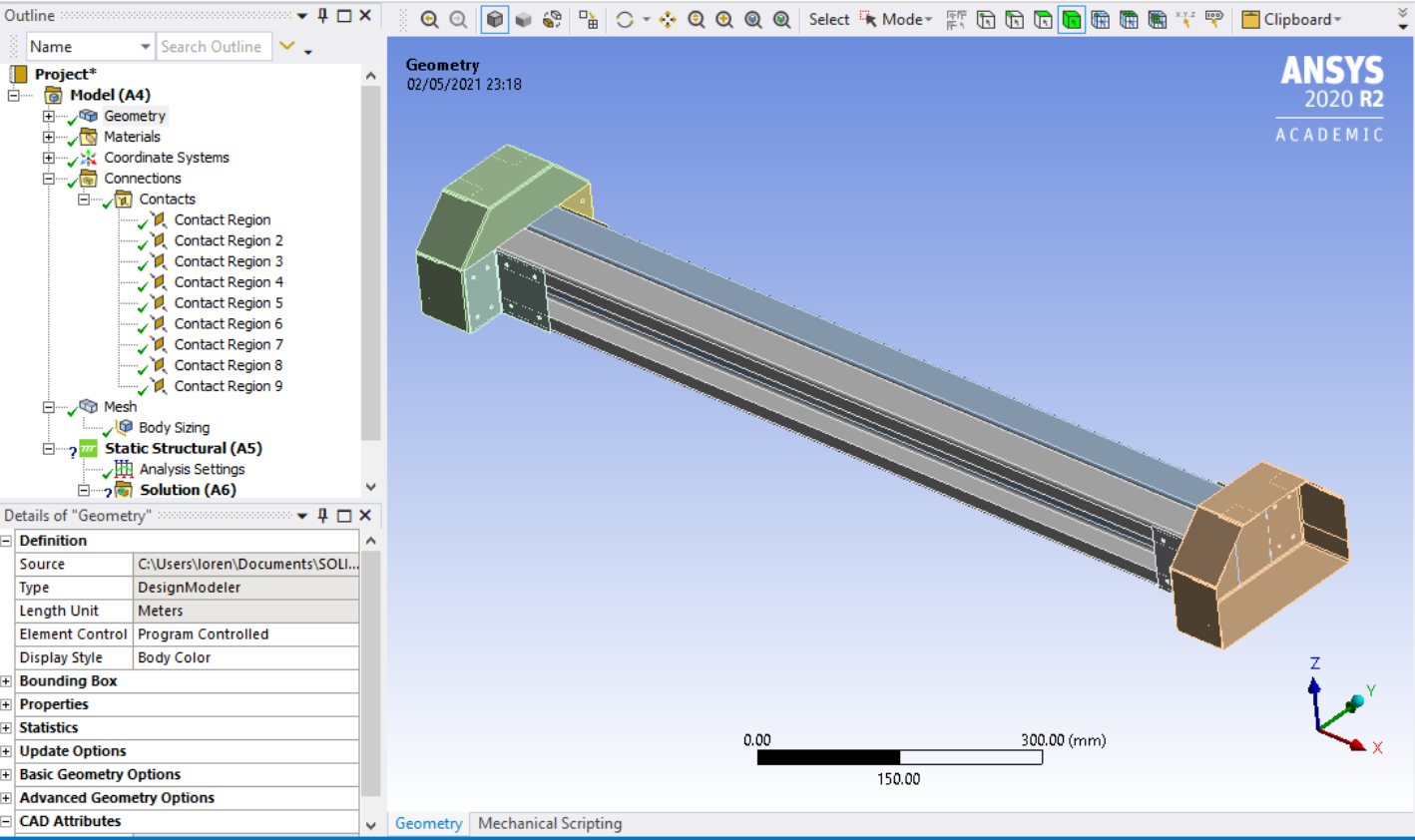
- First of all, gather the assembly 3D model and import that in Ansys Mechanical
 |
 |
|---|---|
| CAD 3D model | 3D model in Ansys |
-
By default Ansys defines contacts between adjacent regions, delete them
-
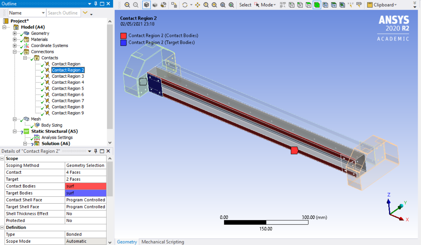
Generate one contact the way you need it
-
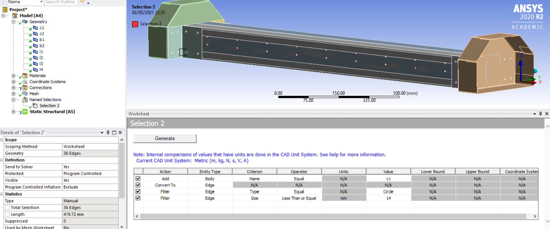
Create a new named selection and set the scope to WorkSheet, then apply the filters and operators you need
 |
 |
|---|
-
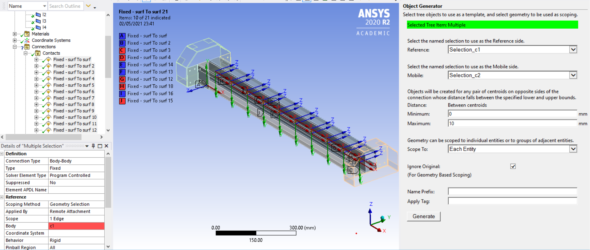
Use the Object Generator to iterate the definition of the custom contact on the elements of the named selections.
-
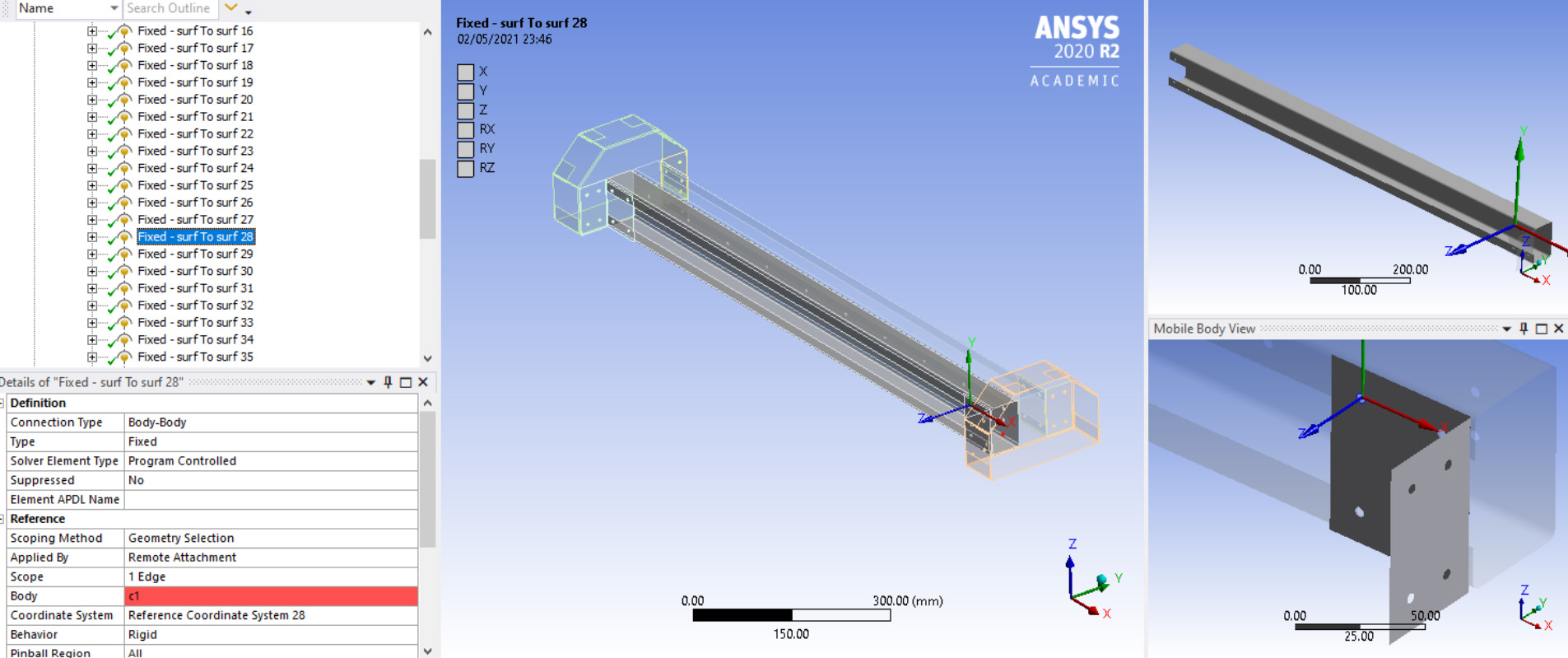
Never forget to check for eventual errors. Computer Aided Engineering does not mean the computer is in charge of design and evaluation errors. For this kind of check I find the body views tool in Ansys particularly useful.
 |
| 
That’s it! I hope this information would be of any interest to anyone facing my same challenge!